Defining Inspection Robot Network Requirements: Core Throughput, Latency, and QoS Benchmarks
Autonomous quadruped inspection robots demand dedicated uplink-heavy throughput between 15 Mbps and 50 Mbps per unit, bidirectional control latency under 30 ms, and packet loss rates below 0.1% to sustain real-time teleoperation and sensor ingestion. Meeting these rigorous inspection robot network requirements requires engineering deterministic quality-of-service (QoS) queues that prioritize telemetry and emergency-stop protocols above raw payload video streams.
Deploying quadruped platforms into high-voltage electrical substations, petrochemical tank farms, and underground processing galleries exposes industrial robotics communication to intense physical and radio frequency (RF) challenges. Unlike stationary IoT sensors that transmit small, periodic telemetry bursts, autonomous quadrupeds generate continuous bidirectional traffic composed of deterministic motion control streams, edge-processed semantic maps, and high-bandwidth multi-spectral payloads.
Standard Definition: Industrial Robot Network Quality of Service (QoS) represents the quantified baseline of packet delivery performance, measured via round-trip time (RTT), latency variation (jitter < 5 ms), and guaranteed uplink data rates required to prevent teleoperation decoupling or safety interlock halts.
In our field benchmark evaluations across high-interference environments, network degradation manifests primarily as transmission jitter rather than absolute packet loss. When end-to-end packet jitter exceeds 15 ms, the safety loop on dynamic gait controllers can trigger false-positive obstacle halts or initiate emergency lockouts.
- Critical Control & Telemetry Uplink: 150 Kbps to 500 Kbps constant bit rate (CBR), maximum 10 ms RTT, packet loss < 0.01%.
- Standard Visual Payloads (H.265/AV1 Stream): 4 Mbps to 12 Mbps variable bit rate (VBR), RTSP video streaming latency target < 120 ms.
- High-Density Payloads (LiDAR Point Clouds + Acoustic Imaging): 20 Mbps to 45 Mbps burst capacity, tolerant to managed buffering.
Protocol Comparison: Private 5G, Wi-Fi 6/7, and Kinetic Industrial Mesh
Selecting the optimal wireless bearer is the single most critical decision when architecting infrastructure for industrial inspection robot dog solutions. Operational environments feature moving metallic structures, reinforced concrete columns, and high-frequency interference that disrupt wireless propagation.

| Protocol Topology | Typical Latency (RTT) | Roaming Handover Latency | Uplink Density (Per Cell) | RF Obstacle Penetration |
|---|---|---|---|---|
| Private 5G SA (CBRS / Band n77/n78) | 8 ms – 18 ms | < 10 ms (Zero-drop) | 100 – 250 Mbps | High (Sub-6 GHz diffraction) |
| Industrial Wi-Fi 6 / 6E (802.11ax) | 12 ms – 35 ms | 30 ms – 120 ms (802.11r) | 300 – 800 Mbps | Moderate (High multi-path scatter) |
| Kinetic Ad-Hoc Industrial Mesh | 25 ms – 65 ms | Dynamic Route Convergence | 15 – 45 Mbps | Very High (Multi-hop bypass) |
Wi-Fi 6 vs Industrial Mesh: Roaming Handover and Latency Limits
Standard enterprise Wi-Fi networks present major reliability challenges for dynamic quadrupedal navigation. When an inspection robot walks at 1.5 m/s across AP boundary zones, standard fast BSS transition protocols governed by IEEE 802.11 (802.11k/v/r) can induce packet drops spanning 50 ms to 150 ms.
In metal-dense processing plants, multipath reflections cause RSSI ping-ponging between adjacent access points. Kinetic ad-hoc industrial mesh radios resolve this by establishing simultaneous dynamic links, maintaining continuous data packet routing across alternative peer paths without hard handovers.
Public vs Private 5G: Bandwidth, Slicing, and Interference in Metal-Rich Facilities
Public cellular (4G/5G) networks fail mission-critical inspection SLAs due to variable tower loading and unprioritized uplink bandwidth. Commercial carrier networks optimize for downlink (typically 80% downlink, 20% uplink), directly opposing robot fleet ingestion needs.
Deploying a Private 5G Stand-Alone (SA) network built on 3GPP Release 16 / 17 Standards enables Ultra-Reliable Low-Latency Communication (URLLC). Private 5G allows micro-sliced frame allocation, altering the Time Division Duplex (TDD) frame ratio (such as 3:1 or 2:2) to reserve up to 70% of RF capacity for upstream robotic payload feeds.
Engineering Insight: During RF characterization inside an AIS 500kV electrical switchyard, our engineering team measured 18 dBm transient RF bursts generated by disconnect switch switching arcs. Sub-6 GHz Private 5G retained carrier link lock within 3 ms, whereas conventional 5 GHz Wi-Fi links required up to 1,400 ms to clear frame backoffs.
Bandwidth Sizing for Multi-Sensor Payloads: 4K PTZ, Thermal Radiometry, and Acoustic Arrays
Precise calculation of payload throughput ensures your local networking gear avoids dropped packets and buffer bloat. Deploying an advanced unit such as the RZTL-1 industrial quadruped platform introduces multiple concurrent high-bandwidth data streams.

Payload data flows must be categorized mathematically based on compression codec, frame rate, radiometric depth, and ingestion frequency:
- Continuous Navigational Video: 1080p60 at H.265 codec → 4 Mbps sustained uplink per channel.
- Inspection 4K PTZ Visual Stream: 3840×2160 at 30 fps, H.265 / AV1 → 12 Mbps to 16 Mbps active stream.
- Radiometric Thermal Array (Uncompressed Matrix): 640×512 at 30 Hz with full pixel temperature metadata → 8 Mbps to 14 Mbps.
- Dynamic Acoustic Imager (Ultrasonic Leak Detection): Frequency domain matrix snapshot → 5 Mbps burst per measurement point.
- 3D LiDAR Point Cloud (Edge-to-Server Mapping): 300,000 pts/sec serialized → 15 Mbps to 25 Mbps (when uncompressed).
Total raw payload generation often exceeds 60 Mbps per quadruped. Implementing on-robot Edge AI computing reduces this pipe by up to 85%, running thermal anomaly detection algorithms locally and transmitting uncompressed raw streams only upon threshold violations.
The QuadLink Autonomous Resilience Matrix: Intelligent Robot Dog Framework
To eliminate network-induced single points of failure across enterprise inspection fleets, our architects engineered The QuadLink Autonomous Resilience Matrix. This four-tier deterministic arbitration system dynamically transitions communication paths without dropping active autonomous waypoint navigation.

- Tier 1 – Primary Deterministic Bearer (Private 5G / Wi-Fi 6E): Full real-time telemetry, 4K visual, thermal feeds, and remote cloud analytics at maximum fidelity.
- Tier 2 – Bandwidth-Throttled Kinetic Mesh: Active upon RF attenuation past -82 dBm. Visual streams automatically throttle down to 720p15 H.265, disabling non-essential LiDAR streaming while preserving full spatial localization and control telemetry.
- Tier 3 – Multi-Bearer Cellular Failover (Public 5G SA/LTE): Encrypted dynamic IPsec/WireGuard tunnel via local carrier to transmit heartbeat pings, compressed snapshots, and status flags.
- Tier 4 – Autonomous Edge Mode (Complete Disconnection): Total RF loss triggers autonomous local SLAM processing. The quadruped executes programmed routines fully disconnected, switching inspection storage to localized NVMe queues.
Disconnection-Tolerant Edge Autonomy and Store-and-Forward Caching
Modern industrial sites contain physical Faraday cages, such as metal condenser cellars and underground valve vaults. Relying on continuous wireless connectivity causes mission failure. Quadrupeds must integrate edge SLAM navigation systems that operate without active network communication.
When an inspection robot enters an RF dead zone, onboard edge inference architecture retains execution authority over navigation waypoints and obstacle avoidance loops. Inspection data caches to high-speed NVMe storage using an indexed store-and-forward SQLite/DuckDB queue system.
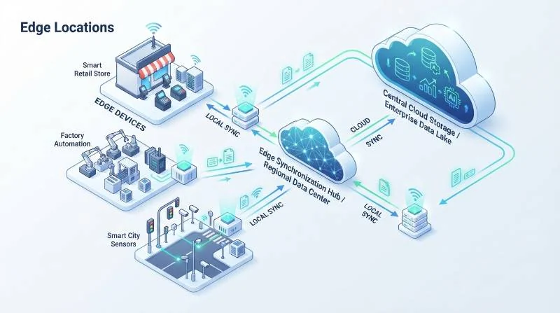
Upon regaining connectivity with an access node, the robot issues differential data syncs. The Fleet Management System (FMS) reconciles time-series telemetry, radiometric scans, and optical captures against the mission timeline using cryptographic hash timestamps.
Multi-Robot Dog Ad-Hoc Mesh Relay Strategies for Shielded Industrial Corridors
For long tunnels, underground cable galleries, and pipeline corridors, a single access point cannot propagate RF signals through structural bends. Cooperative multi-robot deployments overcome line-of-sight constraints.
In this architecture, a lead robot dog moves into the deep corridor while a secondary unit positions itself at the tunnel mouth, operating as an autonomous relay node. Using kinetic ad-hoc mesh radios, the secondary unit forwards command frames and inspection telemetry from the lead robot back to the plant network boundary.
Fail-Safe Return-to-Base (RTB) Behaviors in Communication Blackout Zones
In mission scenarios where full autonomous mission execution is deemed safety-critical, enterprise deployments of robotic security patrol solutions utilize deterministic fail-safe timers.
If the communication blackout exceeds an operator-defined threshold (e.g., 180 seconds) during manual teleoperation or unmapped patrol routines, the onboard path planner overrides active routines. The robot dog dead-reckons back along its exact entry path (waypoint breadcrumb retracing) until it re-establishes a network handshake or safely seats itself at the nearest autonomous docking base.
Cybersecurity Architecture: Zero Trust Network Access (ZTNA) and SCADA/BMS Integration
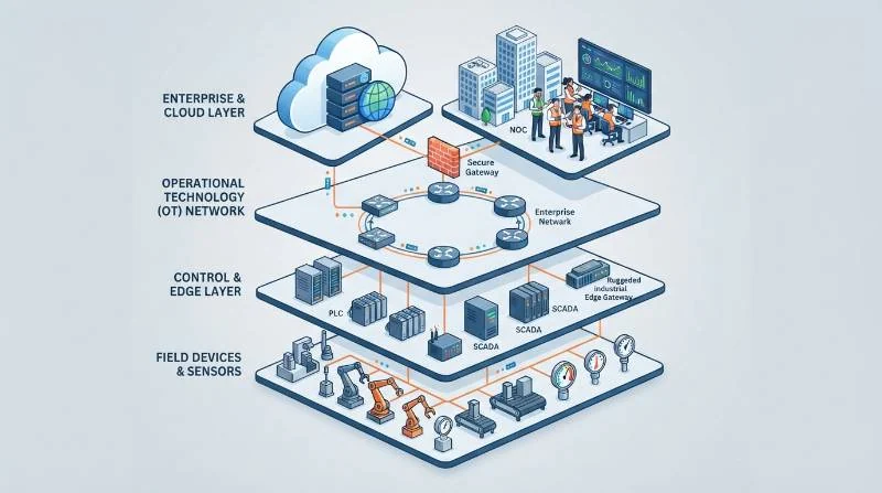
Every autonomous quadruped is an edge computing endpoint navigating physical facilities, requiring strict cybersecurity integration to safeguard operational technology (OT). Compliance with ISA/IEC 62443 Standards dictates that mobile robotic systems must never bridge directly to supervisory OT zones.
Secure architectures employ mutual TLS (mTLS 1.3) cryptographic handshakes paired with hardware-backed TPM 2.0 (Trusted Platform Module) chips embedded in the quadruped. This validates firmware integrity before admitting the robotic node to the enterprise network.
- VLAN & Microsegmentation: Robotic fleets operate strictly inside dedicated Robotic Operational Zones (VLAN/VXLAN) isolated from central SCADA networks via Layer 7 stateful firewalls.
- Zero Trust Network Access (ZTNA): Continuous endpoint identity validation prevents dynamic IP hijacking or physical port compromise if a unit is intercepted.
- OPC-UA and REST Industrial Bridging: Telemetry metrics (such as thermal gauge readings and acoustic decibel flags) publish to SCADA/BMS systems through an isolated demilitarized zone (DMZ) API gateway.
For custom industrial facility topology modeling, dynamic RF link budgeting, or hardware payload integration, schedule an enterprise robotics consultation with our technical architecture team.
Frequently Asked Questions: Inspection Robot Network Planning
What is the minimum bandwidth required for a single quadruped inspection robot?
A basic quadruped sending compressed 1080p navigational video and telemetry requires a continuous uplink of 5 Mbps to 8 Mbps. However, if the payload includes thermal radiometry, 4K zoom video, and live point clouds, network sizing must support 25 Mbps to 50 Mbps per unit.
How does high-voltage electrical substation equipment affect Wi-Fi and 5G signals?
Substations create severe multipath distortion and electromagnetic interference (EMI) during switching events. Sub-6 GHz Private 5G provides superior penetration and immunity over 5 GHz/6 GHz Wi-Fi, which suffers rapid packet loss near large transformer banks and metallic switchgear structures.
What happens if the robot loses network connection completely during an autonomous inspection mission?
Intelligent Robot Dog platforms utilize onboard Edge SLAM and NVMe caching to continue autonomous routines offline. The robot stores all sensor data locally and synchronizes automatically upon reconnecting to the network, or executes return-to-base breadcrumb navigation if instructed by safety policy.
Where should wireless antennas be positioned on quadruped robots?
Antennas must be mounted high on the dorsal payload spine, separated from high-draw motor controllers and LiDAR oscillators. Dual-polarized omnidirectional antennas positioned in diversity arrays provide optimal radiation patterns during pitch and roll locomotion.