The Root Causes of Route Repeatability Failure in Industrial Environments
Route repeatability failure in mobile robots is rarely a path-smoothing issue; it stems from cumulative sensor drift, uncompensated terrain slip, and static coordinate assumptions in changing environments. When an autonomous mobile robot (AMR) navigates an industrial plant, dead-reckoning errors compound quadratically over distance unless continuously constrained by high-confidence physical reference landmarks.
Most inspection failures occur because roboticists confuse trajectory tracking with sensor target alignment. A mobile base might re-enter a 10 cm waypoint radius successfully, but if its yaw angle deviates by just 1.5°, an onboard pan-tilt-zoom (PTZ) camera inspecting an electrical busbar 12 meters away will miss the thermal hotspot entirely.
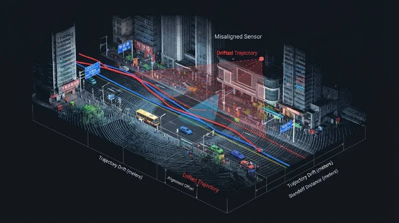
Industrial facilities are dynamic ecosystems. Heavy machinery shifts, forklift traffic creates transient point-cloud clutter, and outdoor environmental factors like rain, mud, and gravel continuously alter ground-wheel traction coefficients. Navigational architectures that rely purely on basic 2D planar LiDAR or standard wheel encoders suffer immediate dead-reckoning breakdown.
Deploying advanced SLAM navigation technology resolves this divergence by decoupling global localization from local ground-truth kinematics, establishing dynamic scan-to-map convergence that prevents long-term spatial warping.
The 4-Pillar Engineering Framework for Route Repeatability
To eliminate route degradation, autonomous inspection routines must be designed against rigorous quantitative metrics rather than visual best-fit paths. Evaluate route repeatability across four essential engineering pillars:
Standard Definition: Route Repeatability (ISO 18646-1)
The ability of a mobile robot to return to a previously taught pose under identical operating conditions, quantified by positional deviation (Δx, Δy, Δz) and orientation deviation (Δroll, Δpitch, Δyaw) across repeated cycles.
- 1. Absolute Localization Drift: The platform must maintain a cumulative position drift rate ≤ ±2 cm per 100 meters of unconstrained traverse before applying loop closures.
- 2. Environmental Robustness: The SLAM front-end must execute real-time dynamic feature rejection to filter out transient objects (e.g., passing personnel, crane movement, steam plumes) and prevent point-cloud corruption.
- 3. Sensor Fusion Latency: The state estimator must fuse raw IMU, LiDAR odometry, and RTK-GNSS inputs at an update rate ≥ 50 Hz, keeping local covariance ellipses minimal during high-speed turns.
- 4. Autonomous Drift Auto-Zeroing: High-precision mission trajectories must integrate automated fiducial landmarks, geometric features, or docking loop closures every 30 to 50 meters to reset accumulated variance to zero.
Kinematics Comparison: Wheeled AGVs vs. Industrial Quadruped Platforms
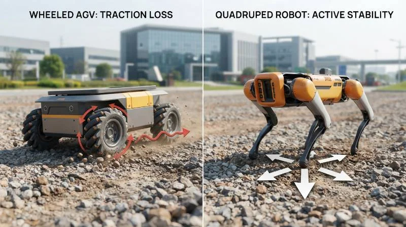
The mechanical interface between the robot and the terrain dictates baseline state-estimation accuracy. Wheeled and tracked autonomous guided vehicles (AGVs) rely entirely on continuous wheel-to-surface rolling contact. On wet steel gratings, uneven gravel, or mud, wheeled platforms experience up to 15% rotational wheel slip.
This slippage introduces false translational velocity data into the Extended Kalman Filter (EKF), forcing the navigation algorithm to heavily warp its local costmap. In contrast, the RZTL-1 industrial quadruped robot utilizes discrete footstep contact mechanics paired with high-frequency joint torque sensing.
| Kinematic Parameter | Standard Wheeled AMR | Industrial Quadruped Platform |
|---|---|---|
| Gravel & Mud Traction Slip | 8% to 15% longitudinal slip | < 0.5% (isolated foothold slip detection) |
| Stair & Curb Navigation | Incapable (requires ramps) | Up to 35° stair angles, 20 cm vertical obstacles |
| State Estimation Input | Wheel encoders + Planar IMU | Leg contact force torque + 6-DoF VIO + 3D LiDAR |
| Waypoint Repeatability | ±5.0 cm to ±15.0 cm on uneven terrain | ±1.5 cm continuous patrol repeatability |
| 5-Year Route Maintenance TCO | High (frequent re-mapping & marker upkeep) | Over 60% reduction via dynamic terrain adaptation |
Quadruped robots calculate kinematic state estimation through instant foot-contact ground reaction forces. If a single foot slips on a patch of oil or gravel, the onboard locomotion controller isolates that single contact point, invalidates its odometry contribution for that step cycle, and maintains state estimation using the remaining grounded feet.
Multi-Sensor Fusion Architecture for Sub-Centimeter Waypoint Fidelity
Single-modality localization systems cannot survive industrial deployment. Sub-centimeter route repeatability requires an integrated sensor fusion pipeline built on a distributed Extended Kalman Filter (EKF) or factor graph optimization engine within the ROS2 Navigation Stack.
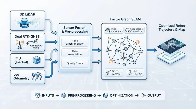
A resilient multi-sensor fusion stack combines four complementary hardware layers:
- Solid-State/Mechanical 3D LiDAR: Generates multi-layer 360° point clouds (300,000+ points/sec) to continuously match local geometry against a pre-surveyed dense point cloud map using Generalized Iterative Closest Point (G-ICP) algorithms.
- Dual-Antenna RTK-GNSS: Delivers centimeter-accurate absolute global positioning (latitude, longitude, altitude) and true heading in outdoor environments, entirely immune to magnetic interference.
- Visual-Inertial Odometry (VIO): High-framerate stereo visual cameras paired with industrial 6-DoF IMUs track high-frequency ego-motion when LiDAR or GNSS experience degraded visibility.
- Legged Kinematic Odometry: Direct joint position, angular velocity, and foot-contact sensor feedback providing continuous high-rate (500 Hz) relative motion estimation.
To adhere to standard benchmarking practices, autonomous navigation architectures should follow the performance evaluation frameworks established by the NIST autonomous vehicle performance standards and ISO 18646-1 robotics navigation benchmarks.
Sensor FOV Alignment and 6-DoF Quadruped Body Pose Trim at Long Standoffs
Achieving millimeter-level data capture across inspection routines requires more than planar base positioning. Base platform angular errors expand linearly with distance, causing serious sensor displacement at typical inspection standoff ranges.
Engineering Insight: Sensor FOV Trigonometric Alignment Formula
The linear target error (Etarget) at a given standoff distance (D) caused by an angular base orientation error (θ) is calculated as:
Etarget = D × tan(θ)
Example: At a standoff distance of 10 meters, an angular orientation yaw error of just 1.2° results in an inspection sensor targeting error of:
Etarget = 10 m × tan(1.2°) = 10 m × 0.02094 = 0.209 m (20.9 cm).
For a narrow Field-of-View (FOV) radiometric thermal sensor or acoustic acoustic imaging camera, a 20.9 cm offset causes complete mission failure. The sensor will capture background concrete rather than the critical bearing housing or insulator pin.
Quadruped platforms solve this problem through 6-DoF body stance trimming. Without moving its foot positions, an industrial robot dog can dynamically adjust its torso roll (±15°), pitch (±20°), yaw (±15°), and vertical stance height (Δz = ±15 cm).
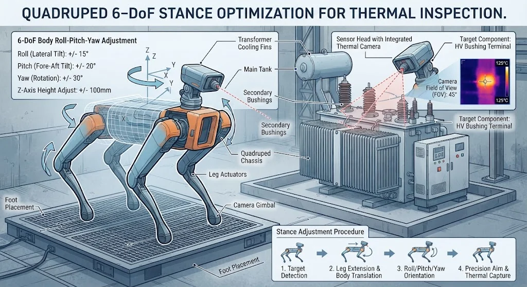
When selecting autonomous industrial inspection solutions, deploying robots capable of body pose trimming allows inspection routines to automatically correct sensor aim without relying solely on mechanical gimbal motors.
Overcoming Environmental Degeneracy: Tunnels, Steam, and High-EMI Substations
Industrial facilities frequently exhibit extreme environmental conditions that break standard SLAM algorithms:
- Geometric LiDAR Degeneracy: Long, featureless tunnels and pipe racks present uniform geometry where point-cloud matching algorithms slide along the axis of symmetry. Mitigate this by enforcing visual feature constraints or placing passive 3D geometric reflectors at 25-meter intervals.
- Dense Steam, Smoke, and Fog: Airborne particulates produce dense, false obstacle clouds in optical and LiDAR spectra. Utilize multi-echo LiDAR sensors and filter return intensities (rejecting low-intensity transient returns while preserving hard asset boundaries).
- Electromagnetic Interference (EMI) in Substations: High-voltage switchyards (up to 765 kV) generate strong electromagnetic fields that corrupt electronic compasses and magnetometers. Pure inertial-magnetic navigation will fail; navigation must rely on dual-antenna GNSS heading and dual-axis LiDAR scan matching.
Detailed performance analyses from operational deployments can be reviewed across our published autonomous patrol deployment case studies.
The 5-Step Intelligent Pose-Constraint Routing (IPCR) Protocol
To ensure consistent route execution, our autonomous systems engineering team mandates the 5-Step Intelligent Pose-Constraint Routing (IPCR) protocol across all field deployments:
Step 1: Dense Geometric Surveying & Global Frame Anchor
Conduct an initial high-density 3D LiDAR survey of the entire facility. Anchor the local coordinate frame to global RTK-GNSS surveyed control points to ensure absolute sub-centimeter alignment between the robotic map and the facility’s engineering BIM/CAD models.
Step 2: Programmatic Waypoint & Kinematic Stance Synthesis
Define inspection waypoints as 6-DoF poses (X, Y, Z, Roll, Pitch, Yaw) rather than simple 2D map coordinates. Explicitly program the quadruped base height and foot spread to ensure a stable stance on slopes, stairs, or grated walkways.
Step 3: Critical Asset Standoff FOV Optimization
Position standoff waypoints to align the payload sensor’s optical center directly along the normal vector of the asset face. Ensure standoff distances remain within the sensor’s calibrated focal length (e.g., 2.5 m to 6.0 m for radiometric thermal sensors).
Step 4: Auto-Recalibration Point Injection
Embed automated drift-zeroing checkpoints every 30 to 50 meters along the route. At these nodes, the robot references persistent structural features (e.g., I-beams, structural columns, or high-contrast AprilTags) to eliminate any residual accumulated SLAM covariance.
Step 5: Dynamic Obstacle Tolerance Matrix Calibration
Configure local path planners with strict spatial clearance zones. Set hard dynamic detour envelopes (e.g., max 1.0 m lateral deviation) around critical assets to prevent the robot from selecting secondary paths that compromise inspection angles.
Validation and Acceptance: The 1-Kilometer Closed-Loop Repeatability Benchmark
Before releasing an autonomous inspection robot into continuous production patrol routines, validate its repeatability against this field acceptance test:
- Test Distance: Execute a continuous 1.0-kilometer inspection loop traversing indoor corridors, outdoor gravel terrain, 30° slopes, and industrial metal stairs.
- Cycle Iteration: Run the full route 10 times consecutively without human teleoperation or manual intervention.
- Target Validation Gauge: Mount a standardized 50 mm circular target optical gauge at 5 critical inspection points across the 1 km course.
- Pass/Fail Criterion: Measure the center point offset of the PTZ inspection camera reticle relative to the 50 mm target gauge at each stop. Target deviation must remain ≤ 20 mm across all 10 consecutive trials.
Any system exhibiting a linear deviation > 20 mm or an angular heading drift > 1.0° requires immediate recalibration of its multi-sensor extrinsic calibration matrices and foot-force state estimators.
Frequently Asked Questions About Mobile Robot Route Repeatability
Why is “teach-and-repeat” insufficient for high-precision thermal inspection?
Teach-and-repeat approaches record an operator’s teleoperated path and retrace the stored trajectory. Because this method records all human steering variances and cannot dynamically account for long-term changes in ground traction or sensor drift, angular targeting errors quickly drift out of tolerance.
How often should LiDAR-Inertial sensor calibration be performed?
In standard operations, spatial extrinsic calibration between the 3D LiDAR and the IMU remains stable for 12 months. However, if the robot experiences mechanical shocks, hardware drops, or extreme thermal cycling (-20 °C to +55 °C), verify sensor calibration every 90 days using an automated target-based calibration routine.
What happens if a dynamic obstacle blocks a mission-critical inspection waypoint?
The local costmap planner attempts an obstacle avoidance detour within a pre-programmed spatial threshold. If the path is entirely blocked, the robot enters a safe holding stance, records the obstruction, and alerts the plant Distributed Control System (DCS) via MQTT or REST API before proceeding to the next waypoint.
Can quadruped inspection routes integrate directly into plant SCADA/DCS systems?
Yes. Enterprise autonomous quadruped platforms support standard industrial communication protocols, including Modbus TCP, OPC UA, MQTT, and secure RESTful APIs, enabling automated data transfers directly into plant asset management databases.
Deploy Precision Autonomous Route Planning with Intelligent Robot Dog
Achieve Flawless Sub-2-Centimeter Inspection Repeatability
Eliminate inspection blind spots, sensor drift, and route failures in your high-voltage substations, chemical refineries, and mining facilities.
Follow our streamlined 3-step deployment path:
- Download the Repeatable Route Planning Checklist for immediate SLAM optimization.
- Request a 3D LiDAR SLAM Route Feasibility Simulation tailored to your facility’s CAD/BIM model.
- Schedule an On-Site Proof-of-Concept Trial with an Intelligent Robot Dog deployment engineer.
Contact Our Engineering Team Today
Or consult with robotics deployment engineers directly to review your facility’s technical specifications.