Architecting Autonomous Patrol: Why Traditional Inspection Robot Deployments Fail
To successfully deploy an inspection robot, engineering teams must execute a four-stage commissioning lifecycle: rigorous site physical and radio frequency (RF) topography surveys, modular multi-sensor calibration, dynamic 3D LiDAR SLAM mapping, and zero-trust SCADA/CMMS pipeline integration. Full autonomy requires moving past manual teleoperation to achieve resilient, edge-computed waypoint execution that survives GNSS outages, severe electromagnetic fields, and adverse weather without operational interruption.
Most industrial robotics pilots stall during field trials. Deploying an autonomous inspection robot fails not due to robotic mobility limitations, but due to poorly architected sensor-to-asset alignment, inadequate environmental mapping resilience in dynamic GNSS-denied settings, and fragmented telemetry integration into legacy SCADA architectures.
When an uncrewed system enters an energized high-voltage substation or a Class I, Division 2 chemical processing unit, theoretical lab navigation collapses. Multipath signal reflections corrupt satellite positioning. High-voltage transients scramble consumer-grade magnetometers, and drifting optical SLAM algorithms leave the robot stranded against open cable trenches or steel grated stairs.
Achieving round-the-clock reliability requires treating the robot not as an isolated gadget, but as an edge node within your facility predictive maintenance stack. Bridging this operational gap demands strict deployment standards, repeatable field protocols, and specialized platforms engineered for non-destructive testing (NDT) across industrial environments.
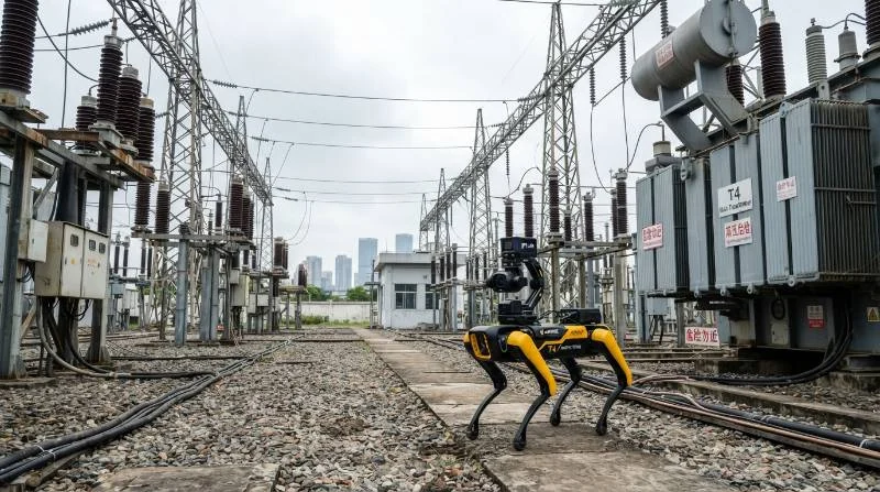
The 4-Pillar Autonomous Quadruped Deployment Index
To establish baseline feasibility before purchasing or unboxing hardware, reliability managers and plant directors must evaluate their facility using the 4-Pillar Autonomous Quadruped Deployment Index. This framework eliminates guesswork and standardizes field readiness metrics across distinct operating domains.
- 1. Geometrical & Electromagnetic Environmental Tolerance: The platform must clear mechanical obstacles such as 35° stair risers, curb steps up to 200 mm, loose gravel beds, and standing water. It must also maintain operational stability under 500 kV electromagnetic interference (EMI) compliant with IEC 61000-6-2 industrial immunity guidelines.
- 2. Mission Payload Fidelity: The robotic payload bus must deliver dual-spectrum radiometric accuracy within ±2 °C (or ±2%), acoustic sensitivity capable of isolating ultrasonic gas leaks down to 0.1 standard liters per minute (SLPM), and edge visual inference running sub-second analog gauge deciphering.
- 3. Docking & Mission Autonomy Ratio: Self-docking precision must fall within ±15 mm mechanical tolerances. The base shelter must offer automated weatherproofing, integrated battery management, and inductive or sealed contact charging that achieves an autonomy ratio exceeding 95% unassisted patrol runs.
- 4. SCADA/MES Enterprise Interoperability: Edge sensor telemetry must stream natively through open industrial protocols—including REST APIs, MQTT brokers, and industrial OPC-UA nodes—directly to enterprise systems without vendor lock-in.
Principal Engineer’s Rule of Thumb: If an autonomous robotic system requires manual intervention more than once every 20 operational patrol cycles, its maintenance overhead neutralizes its operational labor savings. Strict adherence to the 4-Pillar Index ensures your investment yields positive net efficiency.
Phase 1: Pre-Deployment Site Survey and Feasibility Engineering
Field engineering begins long before unboxing the robot. The pre-deployment site audit determines route trafficability, radio frequency (RF) coverage, physical anchor locations, and regulatory compliance perimeters.
Terrain Trafficability: Steel Gratings, Incline Limits, and Substation Gravel
Industrial layouts feature structural obstacles that disable standard wheels or light-duty rubber tracks. Survey engineers must audit:
- Step heights and riser angles: Standard industrial staircases conform to 30° to 38° pitches with riser heights up to 210 mm. Verify that the platform has dynamic gait control to negotiate open-riser galvanized steel grating without snagging toe tips.
- Subsurface conditions: Electrical substations use crushed rock backfill (typically 30 mm to 50 mm granite aggregate) to limit step-and-touch potential during ground faults. The robot must operate on shifting aggregates without losing traction or throwing joint encoder faults.
- Drainage trenches and expansion joints: Uncovered trench spans exceeding 150 mm cause wheeled systems to bottom out. Quadruped platforms step cleanly across these gaps when paired with dynamic step reflex algorithms.
Selecting a robust, field-tested heavy-duty quadruped robot dog platform guarantees that mechanical clearances, joint torque densities, and ground contact kinematics match these structural constraints.
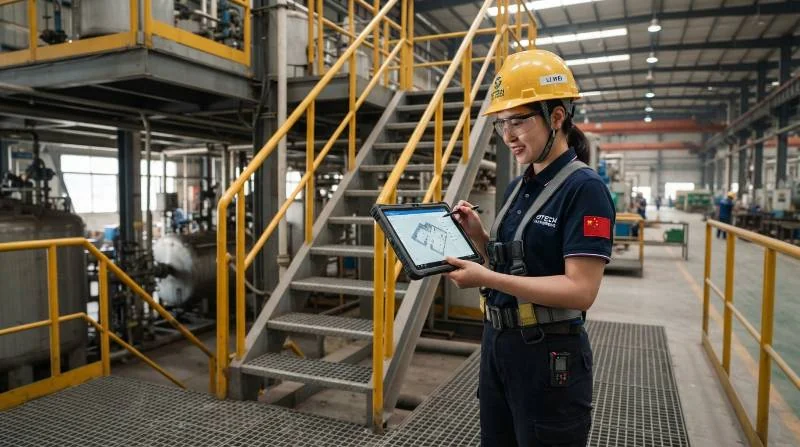
Industrial Wireless Architecture: Private 5G, Wi-Fi 6 Mesh, and Offline Recovery
Continuous edge computing does not eliminate the need for centralized operational oversight. Plant engineers must map RF attenuation across metallic piping arrays, transformer bays, and concrete firewalls.
Deploying a private 5G core or an industrial Wi-Fi 6 mesh network guarantees continuous bidirectional telemetry transfer. Set your design targets to an end-to-end packet latency under 50 ms and packet loss below 0.1% for remote override streams.
Because physical dead zones will inevitably persist in dense containment areas, verify that the robot firmware supports disconnected edge operation. When communications drop, the system must continue executing its LiDAR SLAM inspection path locally, buffer high-resolution radiometric imagery on onboard NVMe storage, and resume upstream syncing upon re-entering signal coverage.
Safety Compliance: ATEX/IECEx Zones and High-Voltage EMI Clearances
Robotic assets operating in hazardous chemical facilities or high-voltage switchyards must comply with site-specific safety envelopes:
- Explosion Protection: In petrochemical processing units, verify whether zones mandate ATEX/IECEx Zone 2 (Gas Group IIA/IIB, Temperature Class T3) certified enclosures, non-sparking foot pads, and overpressurized chassis seals.
- Minimum Safe Approach Distance (MSAD): In utility substations up to 500 kV, configure virtual geofences ensuring the robot mast maintains minimum approach clearances dictated by OSHA 1910.269 and IEEE 516 standards.
- Electromagnetic Immunity: High transient magnetic fields during breaker switching can induce ground loops within unshielded sensors. Platforms must carry IEC 61000-4-3 and IEC 61000-4-8 compliance certifications.
Phase 2: Hardware Configuration, Modular Payloads, and Base Station Infrastructure
Field commissioning requires configuring the mechanical payload interfaces, balancing weight distributions, and establishing autonomous power logistics.
Calibrating Optical, Radiometric Thermal, and Acoustic Sensor Arrays
The utility of an inspection robot depends directly on the quality of its onboard instrumentation. Modern industrial deployments combine multiple sensing modalities into an integrated pan-tilt-zoom (PTZ) sensor payload bus.
Deploying comprehensive autonomous industrial inspection solutions requires aligning three primary sensor channels:
- High-Resolution Optical PTZ: 4K visual sensors with at least 30× optical zoom to read micro-lettering on asset nameplates and identify fluid leaks, physical corrosion, or mechanical wear.
- Uncooled Radiometric Thermal Imagers: Long-wave infrared (LWIR, 8 μm to 14 μm spectral band) sensors with a thermal sensitivity (NETD) under 40 mK and an absolute measurement accuracy within ±2 °C. Regular multi-point blackbody calibration is required to prevent sensor drift in fluctuating ambient temperatures.
- Acoustic Partial Discharge & Gas Leak Detectors: Micro-electro-mechanical systems (MEMS) acoustic arrays spanning 2 kHz to 96 kHz ultrasonic frequencies. These arrays generate real-time visual sound maps that pinpoint pressurized gas escapes or early electrical partial discharge events long before thermal hotspots appear.
Autonomous Charging Dock Siting, Electrical Provisioning, and Weather Shelters
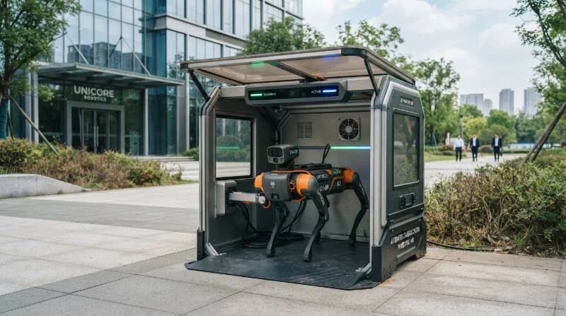
True autonomous patrol requires a zero-touch self-charging station. When specifying base station installation points, adhere to these engineering criteria:
- Power Supply Requirements: Provide an isolated 110 V / 220 V AC dedicated utility supply circuit backed by an uninterruptible power supply (UPS) to guarantee safe docking states during site power outages.
- Environmental Enclosure: Outdoor docks require motorized roll-up doors, IP67 seals, internal dehumidifiers, and thermal-management HVAC units that maintain internal temperatures between 10 °C and 35 °C during extreme seasonal weather.
- Docking Guide Tolerances: While high-precision LiDAR guides the robot toward the station, final mating relies on complementary optical fiducials (AprilTags) and infrared emitter beacons. This dual guidance system ensures the charging prongs align with onboard receivers within strict ±15 mm physical docking tolerances.
Phase 3: Digital Twin Mapping, LiDAR SLAM, and Waypoint Programming
Once hardware is verified, the robot must construct an accurate volumetric model of its operating envelope using Simultaneous Localization and Mapping (SLAM).
Executing Dense 3D LiDAR SLAM in Feature-Poor and Changing Environments
Never rely on 2D LiDAR or pure visual SLAM in heavy industrial spaces. Steam plumes, variable lighting, repetitive piping racks, and moving maintenance vehicles quickly cause visual SLAM tracking to fail.
Instead, use multi-line 3D LiDAR (typically 32 to 128 channels) tightly coupled with an industrial-grade Inertial Measurement Unit (IMU) and wheel/leg odometry dead reckoning. By deploying advanced 3D LiDAR SLAM navigation technology, the platform builds a centimeter-accurate point cloud while simultaneously calculating its own pose.
To prevent spatial drift during initial mapping walks, perform deliberate loop closure maneuvers. Re-crossing previously recorded coordinate vectors lets the underlying scan-matching graph optimizer eliminate odometry accumulation errors across large structural loops.
Waypoint Teaching, Camera Dwell Angles, and Visual AI Gauge Reading Models
After finalizing the baseline point cloud, commission inspection routes via manual teleoperation teach-and-repeat or direct coordinate injection:
- Sub-Centimeter Waypoint Targeting: Pinpoint each inspection stop with sub-centimeter position accuracy and record target yaw, pitch, and roll orientations for the robotic chassis.
- Payload Dwell Routines: At each waypoint, assign the PTZ sensor a specific focus position, focal length, exposure profile, and dwell time (typically 3 to 8 seconds) to capture clean visual, acoustic, and radiometric frames.
- Edge Visual Inference: Configure lightweight edge computer vision pipelines to segment and transcribe critical mechanical indicators on the spot. These models read dial pointers, liquid levels in sight glasses, seven-segment LED displays, desiccant breather colors, and high-voltage disconnect switch positions.
Configuring Dynamic Obstacle Margins, Grate Traversals, and Virtual Keep-Out Zones
An automated plant is a dynamic environment. Workers, parked forklifts, temporary scaffolding, and open equipment hatches can appear along pre-mapped routes without notice.
Configure secondary obstacle detection algorithms using solid-state LiDAR or stereo depth cameras. Set radial safety clearance buffers around the robot dog—typically 0.5 meters for deceleration and 0.2 meters for emergency halts.
Simultaneously program virtual keep-out zones into the navigation layer. These software geofences permanently prevent the robot from stepping close to high-voltage busbars, chemical containment sumps, or fragile cable trays, regardless of what dynamic obstacle avoidance recalculates.
Phase 4: SCADA, DCS, and Enterprise CMMS Workflow Integration
An inspection robot provides little value if its collected data stays trapped inside a standalone vendor cloud. Field telemetry must integrate directly into the facility central control systems.
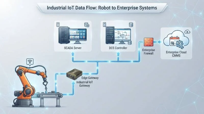
Telemetry Pipelines: MQTT, REST APIs, and Industrial OPC-UA Nodes
To integrate robotics data with legacy industrial control systems, configure standard outbound communication protocols:
- OPC-UA (IEC 62541): Map robot state telemetry—such as battery percentage, active waypoint ID, emergency stop state, and internal temperatures—directly to OPC-UA address space nodes. This lets your Distributed Control System (DCS) treat the robot dog like any standard programmable logic controller (PLC).
- MQTT Sparkplug B: Stream lightweight payload sensor readings and gauge states over MQTT using structured JSON payloads. This provides bandwidth-efficient publishing to local edge brokers and enterprise IoT platforms.
- RESTful Webhooks: Trigger ad-hoc patrol missions programmatically from central supervisory systems when external field sensors detect anomalous plant conditions.
Automated Anomaly Alerting, Trend Analysis, and EAM Work-Order Triggering
Edge processors should continuously compare live telemetry against baseline historical trends. When thermal differentials cross safety thresholds (e.g., a transformer bushing exhibiting ΔT > 15 °C above ambient) or acoustic sensors flag persistent ultrasonic discharge patterns, the system automatically triggers alerts.
Integrate these alarm hooks directly into enterprise asset management (EAM) software like SAP PM or IBM Maximo. The platform automatically generates a high-priority work order, attaches the radiometric thermal image and acoustic signature, and dispatches field technicians before catastrophic insulation breakdown occurs.
Mobility Benchmark: Wheeled Crawlers vs. Industrial Quadruped Robot Dogs
Selecting the wrong drive mechanism often leads to project failure. While wheeled and tracked crawlers work well on flat pavement, legacy industrial sites require dynamic legged locomotion to access elevated platforms and rough ground.
| Performance Metric | Wheeled Inspection Crawlers | Tracked Inspection Units | Industrial Quadruped Robot Dogs |
|---|---|---|---|
| Stair Traversal (35° Industrial) | Non-viable (0% success) | Moderate (high slip risk on wet steel) | Native execution (adaptive gaits) |
| Loose Crushed Rock (Substations) | High immobilization rate | Prone to track derailment | Full multi-terrain clearance |
| Civil Retrofitting Requirement | Extensive ramps and grading required | Moderate curb grading needed | Zero civil modifications needed |
| Docking Repeatability Tolerance | ±50 mm | ±30 mm | ±15 mm (high-precision positioning) |
| 3-Year Total Cost of Ownership | High (due to infrastructure retrofits) | Moderate to High (track wear costs) | 42% lower TCO over 3 years |
Eliminating civil infrastructure modifications like concrete access ramps or metal track guides significantly reduces project start-up costs. Deploying agile quadruped units preserves capital expenditure while providing unhindered access across multi-level sites.
Real-World Deployment Case: 500 kV Substation and Petrochemical Tank Farm
Reviewing empirical field data offers clear insight into long-term system reliability. In a continuous trial across a combined 500 kV transmission substation and adjacent fuel storage tank farm, our engineering teams deployed an industrial quadruped system running autonomous missions twice daily.
The operational environment featured steep steel stairways, 40 mm crushed aggregate yards, severe transformer magnetic fields, and heavy seasonal precipitation. The platform operated with zero human path interventions, demonstrating the value of multi-sensor SLAM navigation.
Empirical Operational Metrics (10,000+ Patrol Hours):
- Patrol Completion Rate: 99.8% across 1,840 scheduled autonomous sorties.
- Thermal Hotspot Identification: Detected 14 incipient disconnect switch defects (ΔT > 18 °C) prior to supervisory protection trips.
- Docking Station Mating Success: 99.6% first-attempt docking accuracy under wind and rain.
- Labor Reallocation: Saved 1,460 hours of hazardous field walking inspections annually.
To examine detailed deployment architectures and real-world system telemetry, explore our collection of substation and hazardous facility case studies.
Industrial Deployment Anti-Pitfall Checklist: Verification & Quality Standards
Before signing off on site commissioning, field application engineers must execute this standardized verification protocol to ensure system reliability:
- [ ] Sensor Redundancy Audit: Confirm navigation does not rely exclusively on optical cameras. Multi-line 3D LiDAR, dual RTK-GNSS receivers, and IMU dead reckoning must maintain sub-decimeter localization even in total darkness or dense fog.
- [ ] Fail-Safe E-Stop Latency Test: Verify wireless emergency stop triggers across all frequency bands, confirming complete motor torque cut-off within 150 ms at maximum walking speed.
- [ ] Adverse Weather Docking Verification: Test automated charging dock returns under simulated heavy rain. Infrared emitters and optical fiducials must maintain a docking success rate exceeding 99.5%.
- [ ] Electromagnetic Immunity Sign-off: Walk the robot within 1.5 meters of energized 500 kV switchgear and power transformers. Confirm that internal joint encoder telemetry, CAN bus lines, and LiDAR point clouds remain free from noise artifacts.
- [ ] Air-Gap Data Buffer Check: Sever external Wi-Fi and 5G connections mid-mission. Confirm that the robot completes its patrol route autonomously, caches all payload telemetry locally, and docks successfully without raising fatal system stops.
Frequently Asked Questions About Deploying Inspection Robots
How long does a complete on-site deployment typically take from unboxing to automated patrol?
A standard industrial deployment takes 3 to 5 business days. Day 1 covers physical site surveys, charging dock positioning, and power hookups. Day 2 focuses on 3D LiDAR SLAM mapping and defining virtual keep-out zones. Day 3 involves waypoint teaching, sensor calibration, and optical AI training. Days 4 and 5 conclude with SCADA/MQTT integration testing, fail-safe validation, and operator handover.
What happens when an inspection robot loses Wi-Fi or private 5G connectivity mid-mission?
The robot continues its pre-programmed route without interruption. Because navigation and AI vision inference run directly on onboard edge compute modules, the system does not depend on a continuous cloud link. Telemetry, thermal frames, and acoustic profiles cache locally on solid-state storage and sync upstream automatically once the robot re-enters network coverage or docks.
How do industrial quadruped platforms handle extreme winter precipitation and icing?
Industrial units carry an IP67 ingress protection rating, sealing all joints and internal electronics against driving rain, blowing dust, and slush. Internal self-heating battery management systems maintain lithium-ion chemistry within safe operational temperatures down to -20 °C. At the same time, high-frequency torque estimation algorithms dynamically counter foot slips on icy concrete.
Accelerate Your Facility Automation with Intelligent Robot Dog
Moving from manual visual inspections to dependable autonomous patrols requires robust hardware, field-proven deployment methodologies, and deep industrial systems expertise. Intelligent Robot Dog delivers turnkey, carrier-grade robotic systems designed to protect mission-critical infrastructure across utility, manufacturing, and chemical sectors.
Follow our streamlined 3-step deployment path to operational readiness:
- Download the Engineering Site Survey Checklist: Audit your facility terrain, RF profile, and electrical clearances using our standardized deployment templates.
- Submit Facility CAD/DWG Layouts: Our autonomous systems engineering team will simulate path plans, payload coverages, and dock placements for your facility.
- Validate System Performance On-Site: Book an interactive live field trial at your facility to see sub-centimeter navigation and automated asset reporting in your actual operating environment.